Acer Ipisb-vr Rev 1.01 Front Panel -
Unlike standard retail motherboards that follow Intel’s Front Panel I/O Connectivity Design Guide, Acer uses a proprietary pinout. Plugging a standard PC case’s power switch into this board without a diagram can lead to a system that refuses to boot—or worse, shorted LEDs.
: Front panel USB ports are separate from this 14-pin block and should be plugged into the yellow headers elsewhere on the board.
Ensure you did not shift the connectors over by one pin vertically or horizontally.
Acer IPISB-VR Rev 1.01 is a MicroATX motherboard originally featured in pre-built systems like the Acer Aspire M3970 Gateway DX4860 acer ipisb-vr rev 1.01 front panel
Section D — Theory and design (4 × 4 = 16 marks) 11. Explain why front-panel cables are often keyed and why manufacturers still include single-pin headers for small switches/LEDs rather than combined multi-pin modules. (4 marks) 12. Discuss ESD precautions when servicing front-panel connectors and why they matter. Provide two practical steps to reduce ESD risk. (4 marks) 13. Describe how an inverted LED polarity connection would appear at power-up and how to correct it without replacing the LED. (4 marks) 14. For a revision-labeled board (e.g., Rev 1.00 → Rev 1.01), list three typical reasons a manufacturer issues a minor revision for a front-panel PCB. (4 marks)
The motherboard is commonly found in Acer desktops like the Aspire M3920 , M3970 , and Predator G3610 .
The saga of the Acer IPISB-VR Rev 1.01 front panel begins with a puzzle: a proprietary header that often leaves builders in the dark because it lacks standard labeling. This motherboard, often found in Acer Aspire systems like the M3970, features a specific 14-pin (or 13-pin, missing one) layout that dictates how your PC breathes life. Ensure you did not shift the connectors over
No Power: If the PC doesn't turn on, ensure the Power SW connector is on the correct pins. You can test the board by briefly touching the two power pins with a screwdriver tip; if it starts, your wiring was likely incorrect.LEDs Not Lighting Up: If your power or hard drive lights aren't working, flip the connector 180 degrees. LEDs are diodes and only work when the electrical flow is in the correct direction.Constant Rebooting: This happens if the Reset Switch is stuck or plugged into the Power Switch pins by mistake. Double-check your placements against the physical layout.
LGA 1155 (Supports 2nd Gen "Sandy Bridge" Intel Core i3/i5/i7). Intel H67 Express. 4x DDR3 DIMM slots; supports up to 16GB at 1333MHz. Expansion: 1x PCIe x16, 1x PCIe x1, and 2x PCI slots. HDMI, DVI, VGA, 6x SATA ports, and 8x USB 2.0 ports. Performance & Compatibility Review front panel pin order Acer IPISB-VR motherboard
The header typically consists of a 14-pin or 10-pin block. For the standard Rev 1.01 version, the layout follows a specific grid. Looking at the motherboard with the CPU at the top, the pins are arranged in two rows. (4 marks) 12
What are you moving this motherboard into?
2 - 4 - 6 - 8 - (Pin 10 is missing/keyed) Bottom Row (Odd Numbers): 1 - 3 - 5 - 7 - 9 Exact Pinout Configuration Pin Number Assignment Polarity Requirement Pin 1 HDD LED (+) Hard Drive Activity Light (Positive) Strict — Must match positive wire Pin 3 HDD LED (-) Hard Drive Activity Light (Negative) Strict — Must match negative wire Pin 2 Power LED (+) System Power Indicator Light (Positive) Strict — Must match positive wire Pin 4 Power LED (-) System Power Indicator Light (Negative) Strict — Must match negative wire Pin 6 Power Switch Connected to Case Power Button None — Orientation does not matter Pin 8 Power Switch Connected to Case Power Button None — Orientation does not matter Pin 5 Reset Switch Connected to Case Reset Button None — Orientation does not matter Pin 7 Reset Switch Connected to Case Reset Button None — Orientation does not matter Pin 9 Unused / Key No connection required Step-by-Step Installation Instructions 1. Identify Wire Polarity


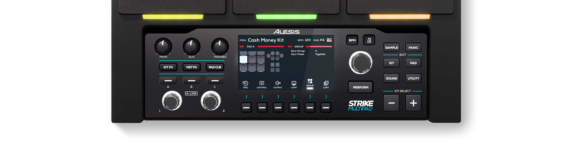
 Video 1: Perform Mode and Looper Overview